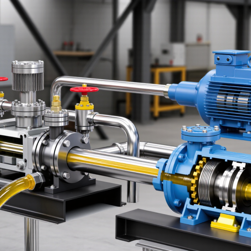
A hydraulic pump converts mechanical input into fluid flow, while a hydraulic motor reverses that process.
The pump generates flow; resistance creates pressure. Pressure is not flow.
A motor receives pressurized oil and produces shaft torque. This distinction helps technicians locate slow movement, overheating, or weak force. The International Energy Agency’s Energy Efficiency 2023 report states that electric motor systems consume roughly half of global electricity. Hydraulic power units often depend on electric motors, so efficiency begins before oil enters the circuit.
Key components
include the reservoir, suction strainer, pump, relief valve, directional valve, actuator, return filter, and cooler. The reservoir stores oil, releases heat, and allows air separation. Gears, vanes, or pistons move oil into the pressure line. A relief valve protects the circuit when a cylinder reaches its limit. Directional valves route flow, while flow-control valves regulate actuator speed. The U.S. Department of Energy’s Improving Pumping System Performance sourcebook reports that pumping systems can represent about 25% of industrial electricity use. Oversized equipment may waste energy through throttling and bypass flow.
During operation, the motor turns the pump shaft.
The pump displaces a measured volume each revolution. Load resistance raises pressure until force meets demand. A cylinder creates linear motion; a hydraulic motor creates rotation. Leakage reduces efficiency and produces heat. Real systems rarely behave perfectly. Oil viscosity changes with temperature, while dirty filters increase pressure loss. ISO 4413 emphasizes pressure control, filtration, guarding, and safe maintenance. Field checks should include pressure, flow, temperature, and electrical input. Sound alone can mislead.



 Close
Close