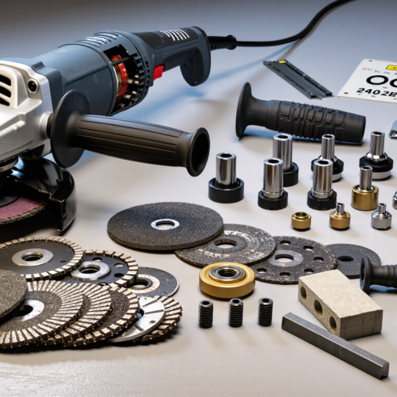
| 1 | Disc diameter | Match the disc diameter to the grinder's specified maximum wheel size. | Use only the diameter stated on the tool rating plate or in the operating manual; never fit an oversized disc. | An oversized disc can exceed the guard capacity and the tool's design limits, increasing the risk of disc failure. |
| 2 | Arbor and mounting dimensions | Confirm the disc bore, spindle thread, flange, and retaining nut dimensions. | The disc bore must seat correctly on the spindle or supplied flange, and the retaining hardware must engage fully without forced fitting. | Incorrect mounting can cause runout, vibration, slipping, or loss of the wheel during operation. |
| 3 | Disc type and application | Choose a wheel designed for cutting, grinding, sanding, polishing, or wire brushing. | Check the wheel's marked application and material suitability, such as masonry, metal, stainless steel, or surface finishing. | Cutting wheels are thin and intended for cutting; they should not be used for side grinding. Using the wrong wheel can cause breakage or kickback. |
| 4 | Maximum speed rating | Compare the disc's maximum revolutions per minute with the grinder's no-load speed. | The disc's marked maximum speed must be equal to or higher than the grinder's rated no-load speed. | Operating a wheel above its rated speed can result in wheel disintegration and serious injury. |
| 5 | Guard size and function | Make sure the guard matches the wheel type and diameter and locks securely in position. | Use the guard specified for the selected accessory; it should not be cracked, loose, obstructive, or modified. | A correctly fitted guard helps contain fragments and directs sparks and debris away from the operator. |
| 6 | Side handle and mounting thread | Check the handle thread, mounting location, grip condition, and adjustment options. | The handle should screw in completely, remain tight during use, and support both left- and right-handed positioning when provided. | A secure auxiliary handle improves control and helps reduce the likelihood of losing the tool during kickback. |
| 7 | Flanges and retaining nut | Inspect the flange faces, nut type, seating surfaces, and compatibility with the chosen disc. | Use clean, undamaged, correctly oriented flanges and the retaining nut intended for that accessory. | Proper clamping distributes pressure evenly and helps prevent disc movement, distortion, or cracking. |
| 8 | Power and electrical compatibility | Verify voltage, frequency, plug configuration, and power requirements before fitting or replacing electrical parts. | Replacement switches, cords, and electrical components must match the tool's rated electrical specifications and connection design. | Incorrect electrical parts may cause overheating, poor operation, electric shock, or fire. |
| 9 | Bearing, brush, and switch replacement | Compare dimensions, connector layout, shaft fit, brush size, and component ratings with the original part. | Use the exact service specification or a documented equivalent; do not rely only on visual similarity. | Small dimensional or rating differences can cause excess noise, arcing, vibration, overheating, or premature failure. |
| 10 | Condition, certification, and inspection | Inspect discs and guards for cracks, chips, warping, corrosion, or missing markings before use. | Select undamaged accessories with legible safety markings and follow the applicable tool and wheel instructions. | Compatibility alone does not make a damaged or improperly marked component safe to operate. |



 Close
Close