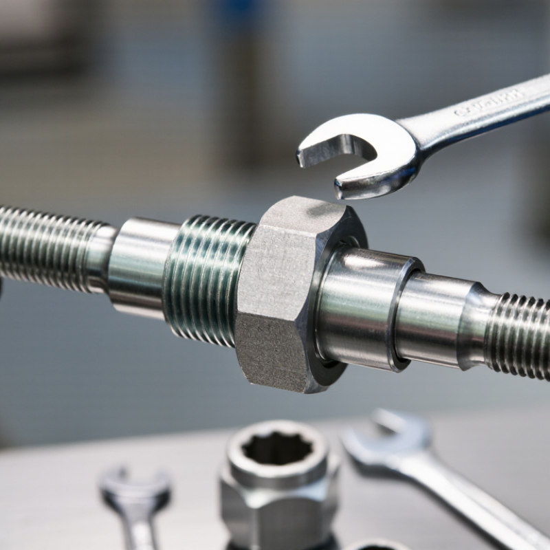
| 1 | Identify the connection | Inspect the two threaded ends and the coupler | A threaded coupler is a hollow fitting with internal threads, or a combination of internal and external threads, designed to join compatible threaded components. | Confirm the thread standard, nominal size, thread direction, and gender. Threads should not be forced together if the pitch or profile differs. |
| 2 | Match thread specifications | Compare diameter, pitch, and thread form | The major diameter is the outside diameter of an external thread. Pitch is the distance between adjacent thread crests. Both must match the mating thread for proper engagement. | For example, an M12 × 1.75 thread has a nominal diameter of 12 mm and a pitch of 1.75 mm. |
| 3 | Prepare the threads | Clean the thread surfaces | Dust, chips, corrosion, paint, or damaged thread crests can prevent full engagement and may cause cross-threading or leakage. | Threads should be clean, free from burrs, and visibly undamaged. Remove loose contamination without altering the thread profile. |
| 4 | Apply sealing method | Use a suitable sealant when required | Parallel threads generally require a separate sealing element, such as an O-ring, gasket, or approved thread sealant. Tapered pipe threads can create a seal through wedging and controlled interference, but sealant may still be required by the application. | The sealant must be compatible with the fluid, temperature, pressure, and material. Avoid applying excess sealant near passages or hydraulic systems. |
| 5 | Start by hand | Align the components and rotate the coupler manually | Hand-starting allows the thread crests and roots to align before torque is applied. The coupler should turn smoothly for several rotations without binding. | Stop immediately if resistance occurs at the first thread or if the parts feel misaligned. This helps prevent cross-threading. |
| 6 | Engage the threads | Turn the coupler until the required engagement length is reached | As the threads advance, the helical surfaces convert rotational motion into axial movement. The mating flanks carry the load while the coupler keeps the connected parts aligned. | Use the specified engagement length for the design. Engagement should be sufficient to transfer the expected tensile, shear, or pressure load. |
| 7 | Apply controlled torque | Tighten with the specified tool and procedure | Tightening torque creates a clamping force between the connected parts. The correct torque depends on thread size, material, lubrication, coating, and engineering requirements. | Use a calibrated torque tool where a torque value is specified. Do not use a generic torque value for every material or application. |
| 8 | Secure the connection | Install a locknut, retaining compound, safety wire, or other approved locking method if required | Vibration, thermal cycling, and repeated loading can reduce preload and cause loosening. A locking method helps maintain the intended connection condition. | Select the locking method according to the equipment design and service environment. Do not combine incompatible chemical products or locking devices. |
| 9 | Inspect the assembly | Check alignment, exposed thread length, damage, and seal condition | A visual and dimensional inspection confirms that the coupler is seated correctly and that the threads have not been stripped, deformed, or left partially engaged. | Look for uniform seating, no visible gaps where a seal is required, no thread damage, and no excessive deformation of the coupler or connected parts. |
| 10 | Test under service conditions | Perform a leak, pressure, load, or functional test as applicable | The completed connection is evaluated under the conditions it is designed to withstand. The test method depends on whether the coupler is used for mechanical, hydraulic, pneumatic, structural, or instrumentation service. | Verify that there is no leakage, unexpected movement, loosening, or abnormal deformation. Depressurize systems safely before making adjustments. |
| 11 | Maintain the connection | Inspect periodically and retighten only when permitted | Environmental exposure, vibration, corrosion, and repeated assembly can affect thread performance and sealing. Routine inspection helps identify degradation before failure. | Replace components with stripped, cracked, heavily corroded, or permanently deformed threads. Follow the equipment maker’s maintenance procedure. |
| Engineering note: Threaded couplers are available in straight, reducing, union, and adapter configurations. Their load capacity and pressure suitability depend on thread geometry, material strength, engagement length, wall thickness, seal design, installation torque, and operating conditions. |



 Close
Close