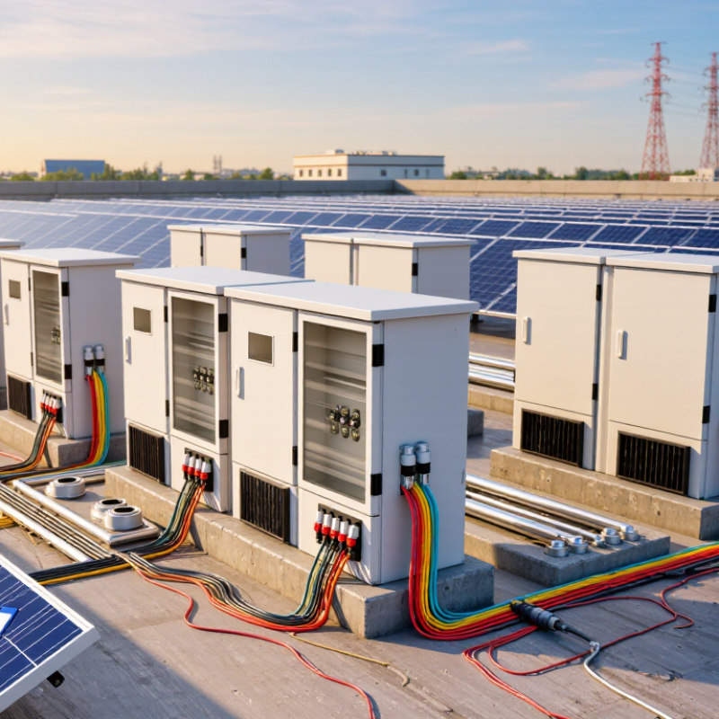
| Primary Function | Combines multiple photovoltaic string circuits into one or more higher-current output circuits before connection to an inverter or other downstream equipment. | Reduces cable quantity, simplifies system wiring, and makes string-level protection and testing more organized. | Confirm the number of inputs, output circuits, and compatibility with the selected inverter architecture. |
| Common System Position | Usually installed between the solar module strings and the DC input of a central or string inverter. | Correct placement helps maintain safe current paths and supports efficient maintenance access. | Review the single-line diagram, cable routes, environmental exposure, and required installation clearances. |
| Number of String Inputs | Common configurations include 2, 4, 6, 8, 12, 16, or more photovoltaic string inputs, depending on system size and design. | The correct input count prevents unused circuits, excessive parallel connections, or later expansion limitations. | Match the box capacity to the actual string count and allow spare capacity only when future expansion is planned. |
| DC Operating Voltage | Typical products are designed for photovoltaic systems in voltage classes such as 600 V DC, 1,000 V DC, or 1,500 V DC. The exact rating depends on the product design. | The voltage rating must exceed the array's maximum open-circuit voltage under the lowest expected temperature. | Verify the maximum system voltage, temperature coefficient calculations, and applicable regional electrical requirements. |
| Input and Output Current | String input current is commonly selected around the module string operating current, while the output current depends on the number of parallel strings and the design margin. | Correct current sizing helps prevent overheating, nuisance tripping, and conductor overload. | Check maximum continuous current, fuse rating, terminal rating, conductor size, and derating for ambient temperature. |
| String Protection | DC-rated photovoltaic fuses may be installed on individual positive or negative string circuits, depending on the array design and protection requirements. | String fuses can limit fault current and help protect modules, cables, and connected equipment from abnormal current conditions. | Confirm fuse type, rated voltage, rated current, interrupting capacity, polarity arrangement, and replacement access. |
| Surge Protection | A DC surge protective device is commonly used to help limit transient overvoltage caused by lightning-related events or switching disturbances. | Surge protection can reduce the risk of damage to inverters and other sensitive DC equipment. | Check the protection class, maximum continuous operating voltage, discharge ratings, grounding method, and status indication. |
| Disconnect or Isolator | Many combiner boxes include a DC load-break disconnect or isolator for system shutdown and maintenance, where required by the design or local code. | A suitable disconnect improves service safety and allows technicians to isolate downstream equipment. | Verify DC switching capability under the intended voltage and current, as well as lockout and labeling provisions. |
| Enclosure Protection | Outdoor photovoltaic combiner boxes are commonly specified with dust- and water-ingress protection such as IP65 or higher, depending on the enclosure design. | Ingress protection helps protect internal components from rain, dust, and outdoor operating conditions. | Select the rating according to the installation environment and confirm that cable glands, doors, and unused openings maintain the rating. |
| Enclosure Material | Common materials include UV-resistant polycarbonate, fiberglass-reinforced plastic, painted metal, or stainless steel. | Material selection affects corrosion resistance, mechanical strength, weight, thermal behavior, and service life. | Consider ultraviolet exposure, salt mist, humidity, chemical contamination, impact risk, and mounting conditions. |
| Operating Temperature | Many outdoor units are designed for a broad ambient temperature range, often approximately -25°C to +60°C, subject to the specific product design and derating requirements. | Temperature affects fuse performance, enclosure heat buildup, cable ampacity, and long-term component reliability. | Request the manufacturer's temperature range, internal heat-rise data, and current derating curve for the intended climate. |
| Monitoring Options | Optional monitoring may include string current measurement, voltage measurement, fuse status, surge protector status, and communication interfaces such as RS-485. | Monitoring can help identify underperforming strings, blown fuses, insulation issues, and abnormal operating conditions. | Confirm measurement accuracy, communication protocol, data integration requirements, power supply, and cybersecurity provisions. |
| Connection Method | Connections may use photovoltaic-rated cable glands, terminal blocks, plug-in connectors, or pre-wired cable assemblies. | Reliable connection hardware reduces installation time and lowers the risk of loose, mismatched, or incorrectly terminated cables. | Check connector compatibility, conductor cross-section, sealing range, torque values, polarity marking, and field-service requirements. |
| Grounding and Bonding | Designs may provide protective earth terminals, grounding bars, or dedicated bonding points for enclosure and equipment grounding conductors. | Proper bonding supports fault-current paths and helps meet electrical safety requirements. | Confirm grounding conductor size, bonding method, corrosion resistance, and compliance with the installation jurisdiction. |
| Applicable Standards | Relevant requirements may include IEC 61439 for low-voltage switchgear and controlgear assemblies, IEC 61643-31 for photovoltaic surge protective devices, and local electrical codes. UL requirements may apply in North American projects. | Standards help define safety, construction, testing, component suitability, and documentation expectations. | Identify the destination market first and request declarations, test reports, certificates, and markings applicable to that market. |
| Factory and Routine Testing | Typical checks may include wiring verification, insulation resistance, dielectric withstand, protective conductor continuity, polarity, torque inspection, and functional testing. | Testing reduces commissioning risks and helps confirm that the delivered assembly matches the approved design. | Request inspection records, test procedures, acceptance criteria, and serial-number traceability. |
| Installation and Maintenance | Important features include clear circuit labeling, accessible fuse holders, hinged or removable covers, spare terminals, and adequate cable bending space. | Good serviceability reduces downtime and improves technician safety during inspection or replacement. | Review installation drawings, wiring diagrams, torque specifications, spare-parts availability, and maintenance instructions. |
| Global Shipping Considerations | Packaging should protect the enclosure, connectors, doors, and internal components from vibration, moisture, impact, and condensation during transport. | International logistics can expose electrical assemblies to long transit times and varied storage conditions. | Confirm packaging tests, export documentation, humidity protection, pallet dimensions, gross weight, and customs classification. |
| Best-Fit Buyer Profile | Utility-scale, commercial, industrial, agricultural, and large off-grid photovoltaic projects with multiple parallel strings. | A combiner box is most valuable when centralized string protection, isolation, or monitoring is required by the system design. | Compare total installed cost, not only purchase price, including cabling, protection devices, labor, commissioning, and maintenance. |



 Close
Close