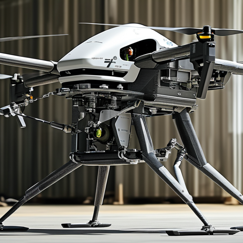
| Frame Layout | Flat central body with six or eight radial arms | Loads from the motors, landing gear, batteries, and payload are transferred through the arms into the central frame plates. | A symmetrical layout helps balance the center of gravity and distributes thrust around the airframe. |
| Number of Motors | 6 or 8 motors | Multiple motors generate vertical thrust and allow the flight controller to control roll, pitch, and yaw by changing individual motor speeds. | An eight-motor arrangement generally provides more actuator redundancy than a four-motor arrangement, but it adds mass, wiring, and control complexity. |
| Arm Material | Carbon-fiber tubes or molded carbon-fiber members | Carbon fiber provides high stiffness and strength at relatively low mass, helping the arms resist bending and vibration. | The fiber direction, tube diameter, wall thickness, joint design, and local impact damage are often more important than the material name alone. |
| Arm Cross-Section | Round, square, or rectangular hollow sections | Hollow sections place material away from the neutral axis, increasing bending stiffness without using a solid block of material. | Round tubes resist torsion well, while rectangular sections can simplify motor-mount and frame-joint interfaces. |
| Central Load-Bearing Structure | Two or more separated structural plates with spacers and bonded or bolted joints | The upper and lower plates form a rigid load path for arm reactions, battery loads, payload forces, and landing impacts. | Spacing between plates increases bending stiffness, but fastener holes and cut-outs must be checked for stress concentration. |
| Redundant Load Paths | Independent arm attachments, paired plates, cross-braces, and multiple fasteners | If one fastener, clamp, or local attachment is damaged, secondary members can help retain the arm and limit progressive structural failure. | Redundancy must be demonstrated by structural analysis and testing; simply adding more parts does not guarantee fail-safe behavior. |
| Thrust-to-Weight Ratio | Common design target: approximately 2:1 maximum total thrust to takeoff weight | Available thrust above hover provides control authority for maneuvering, wind compensation, and changes in payload or battery condition. | The required margin depends on operating altitude, temperature, propeller selection, battery voltage, and the intended flight profile. |
| Payload Integration | Payload mounted close to the center of gravity | Keeping the payload near the center reduces the control moments that the flight controller must overcome. | A low-mounted payload may improve stability but must maintain ground clearance and avoid interfering with landing gear or airflow. |
| Motor Mounts | Rigid plates or brackets secured to the ends of the arms | Motor mounts transfer thrust, torque, and vibration into the arm structure while maintaining propeller alignment. | Mounts should be checked for bolt pull-through, local crushing, fatigue, and loosening under repeated motor torque. |
| Vibration Management | Rigid arms with controlled isolation for flight electronics | The frame carries motor loads while isolation elements reduce high-frequency vibration reaching inertial sensors and cameras. | Excessive flexibility can create resonances, while excessive isolation can allow sensor motion or control-loop instability. |
| Landing Gear Interface | Wide stance with direct attachment to the central frame or dedicated lower members | Landing gear transfers impact and static ground loads into the main structure during touchdown and while carrying a payload on the ground. | The gear should prevent propeller contact with the ground and avoid creating a large bending moment in a single frame plate. |
| Structural Safety Factor | Often selected above 1.5 for ultimate static loads, subject to the applicable design standard | The safety factor separates the predicted design load from the estimated failure load to account for uncertainty and variation. | Fatigue, impact, composite delamination, fastener failure, and manufacturing defects require separate evaluation. |
| Mass Distribution | Concentrated heavy components near the center; arms kept light | Lower rotational inertia allows the aircraft to respond more efficiently to control inputs, while central mass reduces arm bending loads. | Battery placement should also support the intended center-of-gravity range as the state of charge changes. |
| Inspection Points | Arm roots, motor mounts, fastener holes, plate edges, and payload attachments | These areas experience high stress, vibration, or impact and are common locations for cracks, loosening, delamination, or crushing. | Inspection intervals should be based on flight hours, landing cycles, operating environment, and any abnormal event. |



 Close
Close