How to Choose a Telecentric Macro Lens?
Choosing a telecentric macro lens is not merely a matter of selecting the highest magnification. It is a measurement decision. The wrong lens can make a circular part appear larger at one edge than another. That distortion may turn a precise inspection into an uncertain judgment.
Dr. Glenn D. Boreman, an optical engineering author and educator, offers a useful principle: “Measurement quality begins with defining the measurement requirement.” His point applies directly to telecentric imaging. Before comparing brands, identify the object size, working distance, sensor format, required resolution, and acceptable measurement error. A metal washer, molded plastic connector, or semiconductor feature may need very different optical performance. Small details matter.
A telecentric macro lens keeps magnification nearly constant when the object moves slightly along the optical axis. This makes edge measurements more stable. It also reduces perspective errors. Yet telecentricity is not magic. Lighting, focus, sensor alignment, and object positioning still influence results. A lens may deliver excellent specifications but perform poorly in a cramped production cell. That uncomfortable possibility deserves attention.
This guide explains how to compare object-space telecentricity, field of view, depth of field, working distance, and image-circle compatibility. It also considers coaxial lighting, distortion data, mounting constraints, and inspection speed. Some published specifications require careful interpretation. Real samples should be tested whenever possible. A practical choice is rarely the most expensive one. It is the lens that produces repeatable measurements under actual operating conditions.
Define Telecentric Macro Lens Design and Imaging Principles
How to Choose a Telecentric Macro Lens?
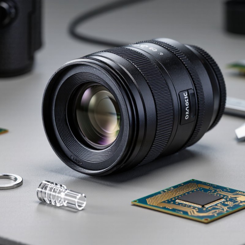
A telecentric macro lens places its entrance pupil near infinity. Chief rays then travel almost parallel to the optical axis. This design creates orthographic-like imaging, so object size changes less when working distance shifts. In production, that matters when measuring holes, edges, pins, or molded parts. A conventional lens may make the near edge appear larger. A telecentric lens keeps geometry calmer.
Choose magnification from the smallest feature and sensor size, not from working distance alone. The lens must cover the full sensor without dark corners. Check telecentricity error, distortion, numerical aperture, and depth of field. Higher numerical aperture improves resolution, but it usually narrows focus tolerance. EMVA 1288 recommends measuring signal, noise, and dynamic range under defined conditions; those figures are more useful than a sharpness claim alone. Very practical.
Grand View Research reported a global machine-vision market value of about 14.9 billion dollars in 2023, with strong projected growth through 2030. That growth increases pressure for repeatable inspection, but a larger market does not guarantee better measurements. I have seen setups fail because lighting was treated as an accessory. Use coaxial or telecentric illumination when surface reflections distort edges. Validate the complete lens, camera, light, and fixture together. A perfect lens can still produce imperfect data.
How to Choose a Telecentric Macro Lens?
Ideal telecentric imaging keeps magnification nearly constant when the object moves along the optical axis. The chart compares the theoretical magnification change caused by a 1 mm object shift at different magnifications.
Assumption: a 100 mm thin lens operating at the listed magnification. For a conventional lens, the approximate relative change is Δm/m ≈ m × Δz/f; an ideal object-space telecentric lens targets approximately 0% change because its chief rays are parallel to the optical axis.
Identify the Required Magnification, Working Distance, and Field of View
Choosing a telecentric macro lens starts with three practical measurements: magnification, working distance, and field of view. Magnification describes how large the object appears on the sensor. A 0.5× lens forms an image half the object’s actual size. Select the lowest magnification that reveals the smallest feature clearly. Higher magnification may improve detail, but it reduces the visible area and can make alignment harder.
Working distance is the space between the lens and the object. Measure it around the real fixture, not only the sample. Leave room for lighting, clamps, and small positioning errors. Field of view depends on sensor size and magnification. Divide the sensor’s active width by the lens magnification for a useful estimate. Check the height as well. A square part may fit horizontally but still be clipped vertically.
Tips: Sketch the object, sensor frame, and working distance on paper. Then test a calibrated target at the intended height. Look for edge distortion and brightness changes. A rushed estimate can fail later.
In practical inspections, I compare the required feature size with the lens resolution and depth of field. Telecentric imaging helps preserve object dimensions when height changes slightly, but it cannot fix poor focus or unstable mounting. Use a longer working distance when access is limited. Still, excessive distance may require more lighting and a larger lens. My own measurements have improved when I rechecked the sensor specifications, because assumptions about sensor size are surprisingly easy to miss.
How to Choose a Telecentric Macro Lens? - Identify the Required Magnification, Working Distance, and Field of View
Practical selection guide based on sensor size, object dimensions, working distance, and inspection tolerance
| Inspection Requirement | Recommended Magnification | Typical Working Distance | Example Sensor Format | Approx. Sensor Width | Approx. Horizontal Field of View | Recommended Use |
| Large component or wide-area measurement | 0.10× | Approximately 100–150 mm | 1-inch sensor | 13.2 mm | Approximately 132 mm | Large parts, tray inspection, dimensional checks with generous field coverage |
| Medium-sized part with moderate measurement detail | 0.25× | Approximately 80–110 mm | 2/3-inch sensor | 8.8 mm | Approximately 35.2 mm | Connectors, molded components, medium-size machined parts |
| Detailed inspection of a small component | 0.50× | Approximately 65–90 mm | 1/1.8-inch sensor | 7.2 mm | Approximately 14.4 mm | Small mechanical parts, printed features, surface-defect inspection |
| High-detail dimensional measurement | 1.00× | Approximately 55–80 mm | 1/1.8-inch sensor | 7.2 mm | Approximately 7.2 mm | Fine edges, small holes, precision profiles, and close dimensional tolerances |
| Very small feature or microscope-level inspection | 2.00× | Approximately 50–75 mm | 1/1.8-inch sensor | 7.2 mm | Approximately 3.6 mm | Micro-features, precision components, and detailed surface analysis |
Magnification Formula Required magnification = sensor dimension ÷ required object-space field of view.
Field of View Rule Object-space field of view ≈ sensor width ÷ magnification. Allow about 10–20% extra margin around the part.
Working Distance Select a working distance that accommodates fixtures, lighting, part height, and robotic or conveyor access.
Selection Notes - Telecentric lenses are preferred when measurement accuracy must remain stable despite small object-position changes.
- Higher magnification generally reduces the field of view and depth of field, so part flatness and focus stability become more important.
- The listed field-of-view values are calculated examples using common sensor widths; actual values depend on the lens design and image circle.
- Confirm sensor compatibility, distortion specification, illumination clearance, and calibration accuracy before final selection.



 Close
Close